Multiple Feedback Filter Design Tool
LC Filter Design Tool Description
LC Filter Design Tool is a web-based application for lumped LC filter synthesis. It is feature rich, user-friendly and available for free from any desktop or mobile device.
Features
- One-click synthesis from a given specifications
- Chebyshev, Elliptic, Butterworth, Bessel or Legendre filter types
- Multiple topologies
- Arbitrary input and output impedances
- Option to use closest capacitor and inductor standard values
Contents
- 1 Introduction
- 2 S-parameters
- 3 Standard Values
- 3.1 E Series
- 4 Export
- 4.1 LTSpice
- 4.2 Qucs
1 Introduction
The RF filter is a two-port linear device used to attenuate certain unwanted frequencies of a signal while passing other wanted ones. The frequency band over which the filter passes through is called the passband, and the frequency band it rejects is called the stopband. The filter frequency response is classified according to its passband and stopband boundaries. The most common ones are:
- Low-pass filter - passes frequencies below a cutoff frequency fc while attenuating frequencies above it.
- High-pass filter - passes frequencies above a cutoff frequency fc while attenuating frequencies below it.
- Band-pass filter - passes frequencies between a lower and upper cutoff frequency fl and fh while attenuating all other frequencies.
- Band-stop filter - attenuates frequencies between a lower and upper cutoff frequency fl and fh while passing all other frequencies.
Along having frequency selectivity, the RF filter is expected to have minimal influence on the pass band phase and amplitude response and maintain good impedance match at each port.
Filters can be implemnated based on several function types. These differ by their passband linearity, roll-off rate and stopband rejection, as well as their component count and sensitivty to component value tolerances. The function types currentlly supported are given below with their 5th order response:
| Type | Gain and Return Loss Response | Phase and Group Delay Response | Advantages and Disadvantages |
|---|---|---|---|
| Butterworth | 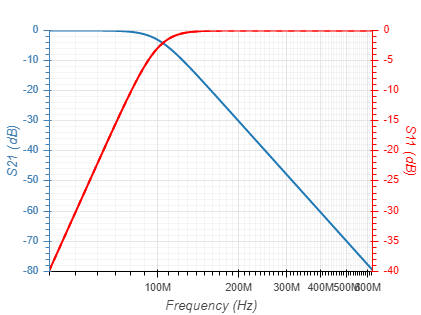 | 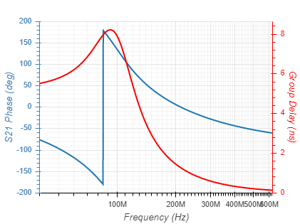 |
|
| Chebyshev (Ripple = 0.1dB) | 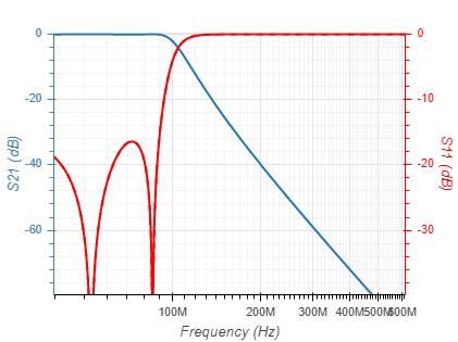 | 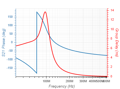 |
|
| Elliptic (Ripple = 0.1dB; Attenuation = 50dB) | 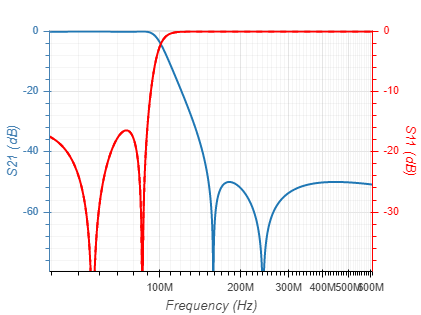 | 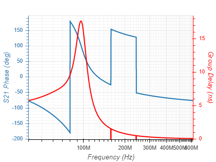 |
|
| Inverse Chebyshev (Attenuation = 50dB) | 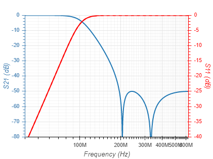 | 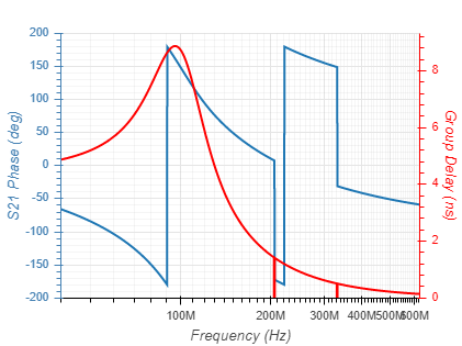 |
|
| Bessel | 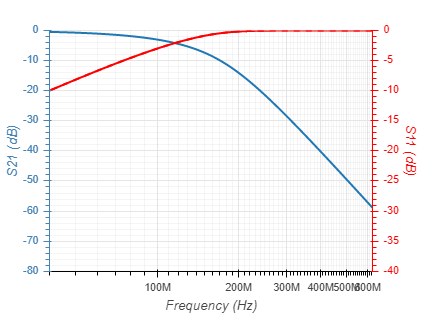 | 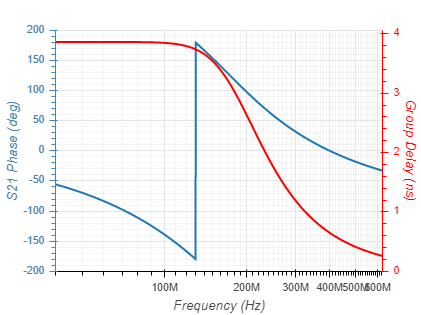 |
|
| Legendre | 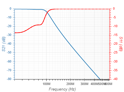 | 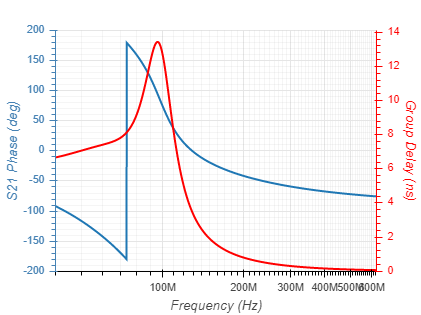 |
|
2 S-parameters
The passive RF filter is a linear device with matched ports, which is typically described in the frequency domain; it is therefore convenient to model its response using s-parameters. An overview on s-parameters is available in Wikipedia. In the present context, the passive RF filters s-parameters consists of a two-by-two complex and frequency dependent matrix, \[ \mathbf{S}= \begin{bmatrix} S_{11} & S_{12} \\ S_{21} & S_{22} \end{bmatrix} \]
Because the device is passive (and non-magnetic) it is also reciprocal, meaning \(S_{21} = S_{12}\) and only three parameters are needed to describe the filter response, \(S_{11}\), \(S_{21}\), and \(S_{22}\). The magnitude and phase of these correspond to several frequency dependent measures important for filter analysis:
| Parameter | Relation |
|---|---|
| Insertion Loss (dB) | \(IL = -20log_{10}(|S_{21}|)\) |
| Input Return Loss (dB) | \(RL_{in} = -20log_{10}(|S_{11}|)\) |
| Output Return Loss (dB) | \(RL_{out} = -20log_{10}(|S_{22}|)\) |
| Phase (rad) | \(\phi = arg(S_{21})\) |
| Group Delay (sec) | \(\tau_{d} = -\frac{1}{2\pi}\frac{d\phi}{df}\) |
3 Standard Values
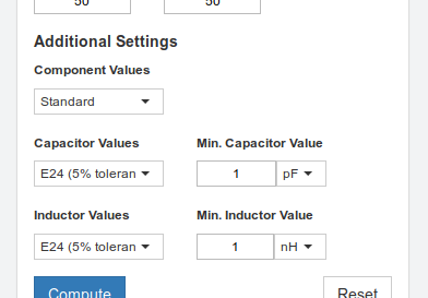
By default, filters are synthesized with exact components values and show ideal frequency response. However, actual mass-produced components have values limited to a set of standard values and bounded below by some minimum; moreover they are subject to manufacturing tolerances and temperature variations. Consequently, when implementing the design, actual component values differ from the nominal values and may negatively impact the filter performances.
To model the filter sensitivity to these variations, the user can limit the capacitance and inductance to E series of preferred values, and also set their minimum values.
3.1 E Series
Each E series values are equally spaced on a logarithmic scale, such that the relative variation/tolerance from the exact value is constant. Below is the list of available E series values and their corresponding tolerances. For more information on E series see Wikipedia.
E6 values (20% tolerance)
1.0, 1.5, 2.2, 3.3, 4.7, 6.8
E12 values (10% tolerance)
1.0, 1.2, 1.5, 1.8, 2.2, 2.7, 3.3, 3.9, 4.7, 5.6, 6.8, 8.2
E24 values (5% tolerance)
1.0, 1.1, 1.2, 1.3, 1.5, 1.6, 1.8, 2.0, 2.2, 2.4, 2.7, 3.0, 3.3, 3.6, 3.9, 4.3, 4.7, 5.1, 5.6, 6.2, 6.8, 7.5, 8.2, 9.1
E48 values (2% tolerance)
1.00, 1.05, 1.10, 1.15, 1.21, 1.27, 1.33, 1.40, 1.47, 1.54, 1.62, 1.69, 1.78, 1.87, 1.96, 2.05, 2.15, 2.26, 2.37, 2.49, 2.61, 2.74, 2.87, 3.01, 3.16, 3.32, 3.48, 3.65, 3.83, 4.02, 4.22, 4.42, 4.64, 4.87, 5.11, 5.36, 5.62, 5.90, 6.19, 6.49, 6.81, 7.15, 7.50, 7.87, 8.25, 8.66, 9.09, 9.53
E96 values (1% tolerance)
1.00, 1.02, 1.05, 1.07, 1.10, 1.13, 1.15, 1.18, 1.21, 1.24, 1.27, 1.30, 1.33, 1.37, 1.40, 1.43, 1.47, 1.50, 1.54, 1.58, 1.62, 1.65, 1.69, 1.74, 1.78, 1.82, 1.87, 1.91, 1.96, 2.00, 2.05, 2.10, 2.15, 2.21, 2.26, 2.32, 2.37, 2.43, 2.49, 2.55, 2.61, 2.67, 2.74, 2.80, 2.87, 2.94, 3.01, 3.09, 3.16, 3.24, 3.32, 3.40, 3.48, 3.57, 3.65, 3.74, 3.83, 3.92, 4.02, 4.12, 4.22, 4.32, 4.42, 4.53, 4.64, 4.75, 4.87, 4.99, 5.11, 5.23, 5.36, 5.49, 5.62, 5.76, 5.90, 6.04, 6.19, 6.34, 6.49, 6.65, 6.81, 6.98, 7.15, 7.32, 7.50, 7.68, 7.87, 8.06, 8.25, 8.45, 8.66, 8.87, 9.09, 9.31, 9.53, 9.76
4 Export
Exporting a filter enables the user to easily:
- Modify the circuit and edit componenet values.
- Run S-parameters analysis.
- Simulate the effects of finite Q inductor.
- Run Monte Carlo analysis.
- Run transient response analysis.
4.1 LTSpice
LTSpice is a free circuit simulation software by Analog Devices. It runs natively on Windows and macOS, and also works well on Linux using the Wine compatibility layer. The latest version is available for download on analog.com.
4.1.1 LTSpice Simulation Settings
The export dialog will create an LTSpice .asc file which includes the filter schematics as well as auto-generated simulation settings. The user can select the type of simulation to preform, either being S-parameters or transient response. On top of that, each simulation can be run with finite Q inductors and/or Monte Carlo analysis.
In the case of finite Q simulation, inductors are modeled as an ideal inductor \(L\) with a small resistor \(r\) in series: The resistnace \(r\) is given by $$r = \frac{2 \pi f_{Q} L}{Q}$$ where \(Q\) in the inductor quality factor and \(f_{Q}\) in the frequency \(Q\) is specified at.
When Monte Carlo analysis in enabled, the simulation is repeated with randomly varing components values. These values are taken to be uniformly distributed within the nominal value +/- the tolerances stated in the export dialog.
4.1.2 LTSpice Examples
- Example 1: S-Parameters
- Example 2: Finite Inductor Q
- Example 3: Monte Carlo
- Example 4: Step and Impulse Response
4.2 Qucs
Qucs is an open-source circuit simulation software. It runs natively on Windows, Linux and macOS. The latest version is available for download on qucs.sourceforge.net.
4.2.1 Qucs Simulation Settings
The export dialog will create an Qucs .sch file which includes the filter schematics as well as auto-generated simulation settings. The user can select the type of simulation to preform, either being S-parameters or transient response.
4.2.2 Qucs Examples
- Example 1: S-Parameters
- Example 2: Step and Impulse Response
© 2017-2021 Marki Microwave, Inc. | Privacy Policy
Multiple Feedback Filter Design Tool
Source: https://rf-tools.com/lc-filter/description.html
Posted by: coxthared.blogspot.com

0 Response to "Multiple Feedback Filter Design Tool"
Post a Comment